Magneto-rheological Finishing (MRF) Applications in Optics

Magnetorheological finishing (MRF) allows ultra-precise manufacturing over a range of optical designs, apertures, and materials at the highest surface quality and sub λ/20 accuracy. With the addition of Q-Flex 300 MRF to its machine park, Solaris Optics added a new level of capabilities to its portfolio. Below we describe main MRF applications in optics from proof-of-concept until today.

First Ever Magnetorheological Finishing MRF Application in Optics

The exciting history of magnetorheological finishing technology, as we know it nowadays, started in Belarus. In 1974 an Ukraine-born Belarussian scientist William Kordonski started his works on magnetorheological fluids. His research had little to do with optics though. Nevertheless in 1986 he learned that a spacecraft project needs aspheric optics for surveillance purposes. Hence, four years later the first MRF machine was ready in Minsk, Belarus. Thereby aspheric lens finishing was the first application of MRF in optics. Still it took almost a decade of R&D works in the USA until the first commercial magnetorheological finishing installation in 1998. The R&D then further continued and the exciting history of MRF technology development and commercialization can be found here.

Today MRF technology is industry-available and has applications throughout the world. The process shall be considered by OEMs and companies interested in high-performance optics. Those who want to ensure their design is converted into physical form without any manufacturing errors. Solaris Optics can support its clients with MRF capabilities across entire product life cycle from prototype to serial production.

Optical Magnetorheological Finishing Basics

Nowadays magnetorheological finishing is a state of art sub-aperture, computer-controlled mechanical process for manufacturing of optical flats, spheres and especially aspheric lenses with high precision and reliability.

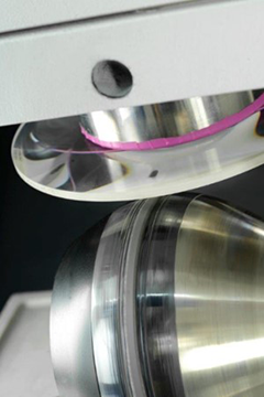
Sub-aperture polishing is defined as removing material from one region at a time, rather than from the entire surface. The material removal is performed using magnetorheological fluids, which are suspensions that contain magnetizable particles and a polishing agent in low-permeability base fluid. An optical element is placed at a distance from a rotating wheel that holds an electromagnet below its surface. The MR fluid is applied via nozzle at the rotating wheel and because of the magnetic field, the particles are pulled against the wheel surface so that a polishing layer is formed on the fluid surface. The position of the workpiece is controlled via advanced algorithms so the workpiece can be machined locally for greater flexibility.

What sets the MRF technology apart is precision fit for most demanding applications, while keeping production times and costs low. It allows manufacturing optics with accuracy and surface roughness quality that can be hardly matched by conventional processes. MRF finished optics can yield figure error down to ~1 nm RMS, mid-spatial frequency errors to ~1 mm and surface roughness to ~1 Å RMS. MRF is also a stable and repeatable process, ensuring high yields and throughput for both unit and serial production.

MRF Applications: Instrumentation, LIDAR, Space Imaging and More

MRF technology offers flexibility for polishing and correction of variety of optics, starting from classic geometries such as spheres and flats to complex ones like aspheric optics or free form optics. Whether it’s creating new components or correcting aberrations on existing lenses or mirrors, this versatility is reflected in wide range of applications it can serve. As in the early-stage example, MRF is widely recognized as a go-to process for high-precision, custom designed aspheric optics. Aspheric optics is harder to produce, but offers lowest wavefront errors and can replace several spherical lenses, resulting in lighter and smaller systems in application areas including medical equipment, scientific devices, high power lasers, space, military and much more.

One of the key MRF applications and markets is in life and health systems, where optics are enablers of sophisticated analytical and clinical uses. This includes broad range of instrumentation, such as microscopy, spectroscopy, molecular imaging, OCT, x-ray and more.

The other promising field of MRF application is LiDAR (Light Detection and Ranging) systems. The LiDar technology is a multi-billion market poised for dynamic growth in the upcoming years. It is used in autonomous cars and advanced mapping solutions. Because accuracy and resolution are key demand for distance and range measurement, especially when user safety is at stake, the performance tolerances for optics are extremely strict.

Another large and dynamically developing market where MRF is oftentimes applied is space systems.

MRF Optics Applications in Solaris Optics – Space

Solaris Optics is the only MRF operator in Poland. We already have a proven track record of using MRF machine for high precision applications, especially for space related uses.

Our flagship project to demonstrate capabilities of MRF process was manufacturing high precision cylindrical mirrors. The mirrors were delivered to the second largest optical-infrared space observatory in the world (Paranal Observatory). Using MFR with combination of stress mirror polishing, five mirrors were produced with full aperture PVr of just 22.4 nm. More on this project MRF Polishing for Manufacturing Optical Cylinders.

Yet another application where Solaris Optics applied MRF is manufacturing of imaging optics for a super tele-objective, a system aimed at Earth observation from space. This time we reduced the dimensions and weight of the system by aspherizing lens surfaces with MRF. See more here Super Tele-Objective for Earth Observation.

The projects are examples how well MFR process can adapt to existing machine park to meet most demanding optical requirements. As we can also see, today’s MRF applications in optics have not come far away from its root uses.
 

***

MRF Polishing for Manufacturing Optical Cylinders

Case Study: Manufacturing high precision mild cylinders with MRF polishing and stress mirror polishing

In the following article we describe a case study where MRF polishing was used to correct astigmatic operation of an optical cylinder.

Space telescopes are some of the most demanding applications when it comes to the quality of optical elements. The precision and accuracy required can be matched only when using most advanced manufacturing technologies. Solaris Optics took part in a project to deliver mirrors for the coude train of the auxiliary telescopes at Paranal Observatory, the second largest optical-infrared observatory in the world by light-collecting area.

The project was a collaboration of Solaris Optics, Military University of Technology (Warsaw, Poland) and QED Technologies (Rochester, NY, USA), a developer of manufacturing and metrology solutions for the optical industry.

Solaris Optics task was to manufacture a high-precision cylindrical mirror used to compensate for the astigmatic aberration in the system. The main objective was to reduce surface error much below full aperture specification. For reflective optics, this means that the fabrication process must be performed with strict control of the overall mirror figure and surface smoothness. Any imperfection leads to aberrations affecting the overall performance of the optical system.

Space Telescope Strict Requirements

Produced from Zerodur, a glass-ceramic composite widely used in earthbound and space-borne telescopes, the geometrical specification for the mirror included a diameter of 204 mm and a cylinder radius of 191 meters, which corresponds to sag 26,178 microns. The specification demanded surface error shall be kept under 65 nm PV over the full aperture. Such strict requirements demand the highest precision of the fabrication and measurement process. Equally important was how to make the process efficient, so the elements can be done promptly and at a reasonable cost.

Questions regarding MRF polishing for your application? Click here, we are happy to answer your questions!


Stress Mirror Polishing to Precede MRF Polishing

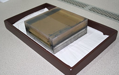
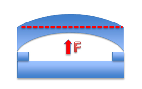
In the first step, flat and plano Zerodur block was used to form a preliminary cylinder surface using stress mirror polishing (SMP), a fabrication technique in which material removal is performed while the material block is deflected.

The block first is glued to a bending fixture which is then deformed to the inverse of the desired aspheric surface. In the next step, the mirror surface is polished flat. After the load is removed, the elasticity of the material makes the surface spring back to the desired form. In the last step, the block is rounded to the final 204 mm diameter. The advantage of this method is simplicity and high removal rate. Nevertheless for more demanding applications further finishing, such as Magnetorheological Finishing, needs to be applied.

Magnetorheological Finishing MRF to Exceed Precision Specs

Magnetorheological Finishing (MRF) technology, the second production step, was the key to reduce residual error to desired levels after the stress mirror polishing process. The technique uses a stream of magnetically-sensitive smart fluid as an abrasive. The workpiece is placed at a distance from a rotating spherical wheel. The electromagnet inside the wheel generates a magnetic field that pulls the stream of magnetorheological fluid to form a sheared layer of polishing fluid between the wheel and the piece. As the wheel rotates at high velocity, the magnetorheological fluid is pressed against the fabricated surface, hence performing material removal. MRF polishing is a subaperture technique, as the polishing tool comes in contact with only a small area of the mirror’s surface.

For other applications of Solaris Optics MRF polishing machine click here.

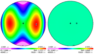
Sophisticated software controls the process to ensure stability and repeatability of every polishing cycle, allowing for finishing optics to < λ/20 PV demanded by space telescope applications. For the manufactured cylinders, MRF polishing reduced the full aperture PVr from 5.38 µm after stress mirror polishing to just 22.4 nm, way below specified 65 nm. This high surface quality was achieved without any significant edge effect.

Metrology of Space Telescope Cylindrical Optics

The manufacturing process for cylindrical optics is more complex than for spherical elements. This requires high standards from quality control systems. The SMP stage was verified using high-accuracy coordinate measuring machine (CMM), a process that yields precision but needs to be performed carefully as to not damage the element. During the MRF polishing, Solaris Optics team used Subaperture Stitching Interferometry (SSI) for proper control of the polishing process between the cycles. SSI is a non-contact measurement technique that allows precise measurements of high aperture optical elements. It combines multiple subaperture phase shapes into a full-aperture phase map with the use of stitching algorithm. The novelty in the project was measuring cylindrical surface as a deviation from flatness.

MRF Polishing Enables Cost-efficient Manufacture of High Precision Mild Cylinders

The project tested both know-how and equipment capabilities of Solaris Optics and the results were beyond positive. The process developed by the team allowed for precision cylinder mirrors to be manufactured cost-effectively and predictably. The fabrication flow proven to exceed the required specification, ensuring stable parameters for all the five mild cylinders produced in the scope of the project. A combination of efficient stress mirror polishing and high-precision MRF polishing processes resulted in cost- and time-efficient fabrication without sacrificing quality.

***

About the Project

Manufacturing high precision mild cylinders using classical stressed mirror polishing, MRF™ and SSI technologies
Part of the project for ESO Paranal Observatory: Manufacturing, Test and Delivery of Mirrors for the Coude Train of the Auxiliary Telescopes
Bartosz Szterner1, Mariusz Bienias1, Marek Broda1, Grzegorz Fluder1,
Chris Maloney2, Paul Dumas2, Jean Pierre Lormeau2,
Sławomir Gogler3, Arkadiusz Swat
1 Solaris Optics S.A. company, Józefów, Poland
2 QED Technologies Inc., Rochester, NY, USA
3 Institute of Optoelectronics, Military University of Technology, Warsaw, Poland

***

Super Tele-Objective for Earth Observation

Tele-objective is an optical lens system that allows to achieve focal lengths longer than the lens itself. It enables viewing objects in high resolution from a long distance. Such a mix of features is much appreciated in photography, but also in other fields, including e.g. Earth observation.
 
A consortium of Polish entities, led by Solaris Optics, has recently reported results of a joint project for the European Space Agency (ESA). The project was issued within Polish Industry Incentive Scheme, which is an ESA program aiming at ramping up cooperation with Polish industry.
The aim of the project is to design and build a demonstrator of an Earth observation optical system. A system that shall be operated on an Earth orbit in the future.
 

The Space Challenge

Space equipment typical requirements, such as light weight, small size and rigidity, are binding also for the tele-objective design. Requirements towards optical performance of the tele-objective include high resolution from a long distance, high image quality, as well as a specific spectral range (wavelengths longer than 450 nm and shorter than 700 nm hence covering the visible light). The design distance between the lens and the low Earth orbit (LEO) was 540km.

Hence the overall challenge and question was, whether all the initial requirements can be met on the design and, later, manufacturing domain. The ESA project started with Phase 1 – design & modelling. Depending on Phase 1 results, Phase 2 – building a demonstrator, can be ordered.
 

Consortium for Space Tele-Objective

Solaris Optics took a leadership role in a consortium cooperating within the ESA project. The other partners include Space Research Centre (CBK) and Institute of Electronics Materials Technology (ITME). The roles of consortium partners were assigned as follows:
– Solaris Optics – project lead, design, modelling and manufacturing of the tele objective. Additionally the tele objective shall be integrated, assembled and optically tested by Solaris Optics.
– Space Research Centre www.cbk.waw.pl is responsible for design and manufacture of mechanical elements of the tele objective, its integration, mechanical and environmental testing.
– Institute of Electronics Materials Technology www.itme.edu.pl task was to manufacture and design of large area diffractive elements, as well as integration of the tele objective.

Super Tele-Objective Optical Design

On the concept development stage, Solaris Optics modelled several optical setups, including mirror-based (catoptric), mirror-lens (catadioptric) and lens-based (dioptric). Such analyses showed that optimum tradeoff between dimensions, resolution and image quality can be achieved with a dioptric, refractive design.

Tele objective design
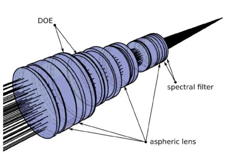
Figure 1 – Super tele-objective design

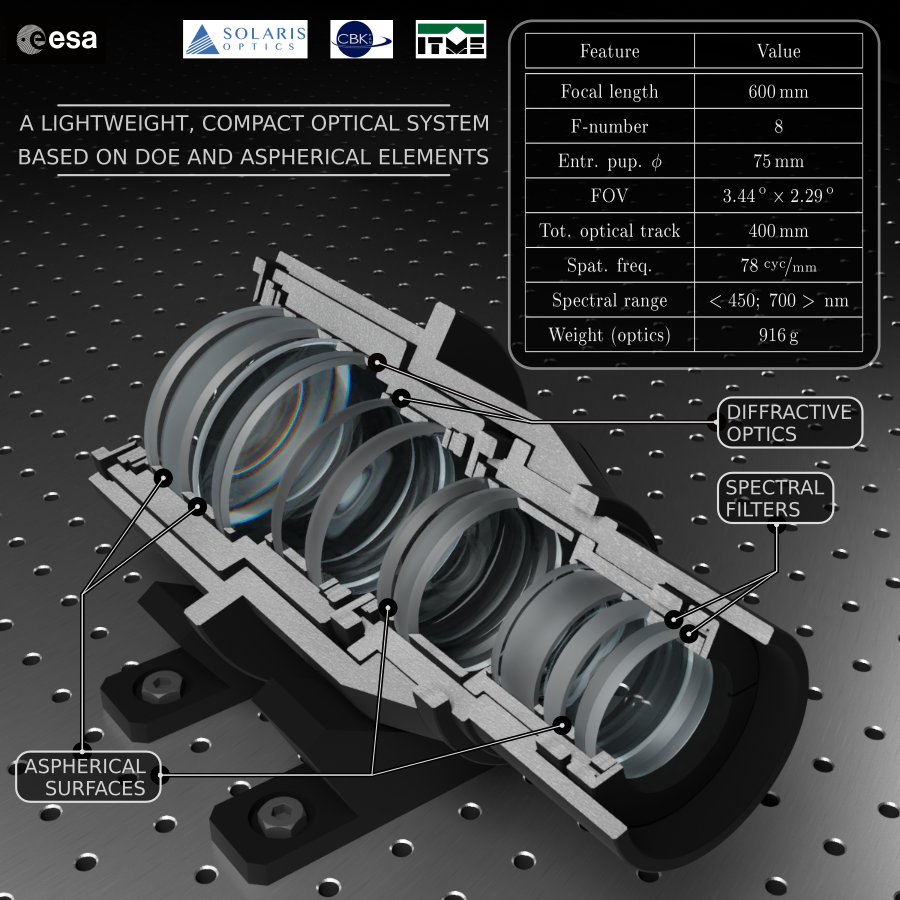
The actual specific outcome was a refractive-diffractive design: a composition of aspheric lenses, diffractive optical elements (DOE) and filters (see Figure 2). Aspheric lenses allow to limit the number of optical elements (hence to limit the total weight) while keeping imaging resolution within acceptable values. DOEs, functionally designed by Solaris Optics, allow to correct the sphero-chromatic aberration with a negligible weight. A set of AR and UV filters secures the required spectral throughput, i.e. wavelengths shorter than 450 nm and longer than 700 nm are filtered out.
 
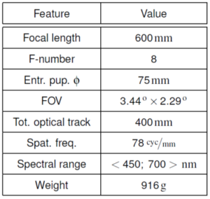
The focal length of the designed optical system (600 mm) positions the tele-objective in a “super” class, hence a “Super Tele-Objective”. Its total achieved weight (the optical elements) is as low as 916 grams.

Optical characteristics of the super tele-objective for Earth observation is presented in Figure 2.
 

Super tele objective parameters
Figure 2 – Super tele-objective parameters

Manufacturing of Key Optical Elements

All the modelled and designed components are to be manufactured by the consortium partners:
– lenses, aspheric lenses and filters – by Solaris Optics,
– DOE components by ITME,
– mechanical housing for the system – by CBK.

Aspheric lenses will me manufactured by Solaris Optics using Magnetorheological Finishing (MRF) technology.

“Our technology team has been successfully using MRF for several years now. Typical application of MRF is ultra-fine corrective polishing of optical surfaces. However in this specific application we use MRF to manufacture the designed aspherical surfaces” tells Jerzy Krężel, PhD, R&D Manager at Solaris Optics.

For spectral filters Solaris Optics will use its Physical Vapour Deposition – Plasma Ion-Assisted Deposition (PVD-PIAD) chambers. PVD-PIAD allows to achieve AR coatings with <1% reflectivity, with materials suitable to space mission requirements.  

Solaris Optics Ready to Provide Optics for Space Applications

The project has been recently reported and presented to ESA. The agency executed its Manufacturing, Assembly, Integration and Test (MAIT) Plan Review and requested Phase 2 of the project. Phase 2 includes building a demonstrator and turns the super tele-objective project into production phase. The Phase 2 order is also a successful conclusion of the works delivered by all consortium members.

“Start of cooperation with ESA was a big opportunity for us to show our competence in demanding applications, such as space missions and Earth observation. Ordering of Phase 2 proved our optical design capabilities and shows also ESA trust in our manufacturing capabilities. I am sure we will succeed in the next phase and I am looking forward to it” said Michal Muniak, CEO of Solaris Optics.

Meanwhile the production phase has already started. The lenses, filters and DOE components will be manufactured, assembled, integrated and turned to final tests.

As the final step the consortium will look for opportunities to bring the super tele-objective to the Earth orbit.

***

About

More about imaging optics from Solaris Optics
 
SPACE RESEARCH CENTRE
The Space Research Centre of the Polish Academy of Sciences activity is dedicated to the research into terrestrial space, the solar system and the Earth using space technology and satellite techniques. Since 1991 it has cooperated with the European Space Agency (ESA). The SRC has also collaborated with NASA (IBEX mission and Chandrayaan mission).
 
INSTITUTE OF ELECTRONICS MATERIALS TECHNOLOGY
The Institute of Electronic Materials Technology (ITME) is a research, development and consultative institution offering a unique combination of scientific and technological capabilities. The R&D activities of ITME include processing of advanced materials (e.g. graphene, mono-crystals, thick-film materials, opto-, piezo- and superconductor-electronics, etc.) and devices based on these materials.

***