KDDP Pockels Cells – Operation and Design
Published: November 5, 2021
The purpose of this technical description is the presentation of basic principles of modulators using the linear electro-optic effect in KDDP crystals – it discusses specifically KDDP Pockels cells. It can be helpful for laser system designers and can especially stimulate proper technical solutions and applications of the electro-optic effect for modulation problems.
KDDP Pockels Cells – Principle of Operation
The operation of Pockels electro-optic modulators is based on the principle of electrically induced birefringence in anisotropic crystals. The optical properties of these crystals are described by index ellipsoid. For Pockels effect, the variation (∆) of these indices of refraction (ni) is proportional to the applied electric field (Ei) and they are related by tensor of electrooptic coefficients (rij ) :
∆ (1/ni2) = ∑ rij Ej
Tensor rij describes electrooptic properties of the crystal. This tensor, of rank 3, contains 18 electro-optic coefficients rij describing electrically induced birefringence in the crystal. However, in optical crystals, many of these coefficients are equal to zero. The number and values of the rij coefficients will determine the possibility of application to the modulation of laser beams.
From many crystals belonging to twenty classes of symmetry, in practice, only a few crystals are used for the Pockels cells design. They are birefringent crystals. When an external electric field is applied, the natural birefringence of the crystal changes. This deforms the index ellipsoid of the crystal and the uniaxial crystal becomes biaxial with new induced indexes of refraction. The input optical beam splits into two orthogonally polarized components propagating in a crystal with different velocities, determined by new induced refractive indices. Induced birefringence ∆n is proportional to the applied electric field and on the crystal length L gives controlled phase retardation Γ between these components :
Γ = 2π ∆n L / λ
where: λ – wavelength of the optical beam.
The voltage sensitivity of the Pockels cell is described by the half-wave voltage (U λ/2 ). This is the voltage required to obtain a phase retardation Γ of 180°.
For Z-0 cut XDP crystal family half wave voltage for longitudinal Pockels cell is given by the following relations :
U λ/2 = λ /2n03r63
where :
n0 – index of refraction for ordinary ray,
r63 – electooptic coefficient
For Z-45° cut crystals of XDP family, used for transverse Pockels cells, the half wafe voltage is given by :
U λ/2 = λd /2n03r63L
where :
L – crystal length,
d – the distance between electrodes.
Modulation of the optical beam is realized by using Pockels cell and suitable polarizing elements such as Glan-Thompson, Wollaston prisms, thin-film polarizers and others. Optical beam of intensity I0 passes through the input polarizer which produces linearly polarized light. The output polarizer (analyzer) can be either crossed to the input or parallel. In the case of crossed polarizers, voltage U applied to the cell and output beam intensity I are related by :
T = I/I0 = k sin2 (πU/2 U λ/2 )
where :
T – relative transmission,
I0 – input intensity,
k – loss coefficient (k<1).
Design of KDDP Pockels Cells
Pockels cells are used in laser technology to control the parameters of laser radiation both inside and outside the laser resonator. Outside the resonator Pockels, cells are used as fast optical shutters. They are used for shortening Q-switched pulses up to nanosecond duration as well as for the selection of single ps and fs laser pulse from the mode-locked train of pulses. Inside the resonator, Q-switching technology is commonly used as a method to achieve high power laser pulses, especially in solid-state lasers.
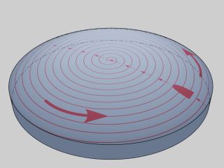
All these applications show, that the Pockels cell must be able to hold high power densities of laser beam and must be fast in operation. In the visible (VIS) and near-infrared (NIR) spectral range, for Pockels cell designs are used at present the following basic crystals: KDDP, LiNbO3, BBO and also KTP and RTP. Active elements for cells are fabricated as rods with a round shape with axis along the optical axis of the crystal (Fig.1), or as rectangular rods with the faces perpendicular to the main crystallographic axes. There are two basic configurations used for electrooptic modulation: longitudinal and transverse electrooptic effect. The configuration used in practice depends on the matrix of electrooptic coefficients rij for the crystal.
Up to now, KDDP (KD*P) Pockels cells are especially widely used in laser technology. The rij matrix for these crystals has 3 non-zero coefficients: r41, r52 = r41, and r63. So, both longitudinal and the transverse electrooptic effect can be realized here. Longitudinal effects in KDDP crystals have found the widest application. In this configuration (Fig.4), the direction of the electric field is parallel to the direction of the laser beam and the optical axis of the crystal [1], [2]. In practice, to implement the longitudinal effect, cylindrical ring electrodes are used on the side surface of the KDDP crystal with the Z – 0 cut (Fig.1).
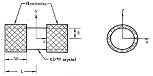
Fig.1. KDDP crystal with Cylindrical Ring Electrodes (CRE).
With such a configuration of electrodes, it is impossible to obtain a homogeneous electric field in the crystal [1] – [4]. That is a source of specific nonuniformity of transmission in the crystal cross-section. In order to obtain nonuniformity of the field distribution in the crystal <5%, the length of the crystal (2L) must be at least twice its diameter (2R). With such crystal dimensions, the width of the electrode W must be sufficiently large. For W / L = 0.65 – 0.7 it is possible to obtain field nonuniformity in the crystal dU = 3 – 4% when L / R = 2 or more ( Fig. 2 ).
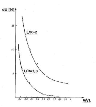
Fig.2. Nonuniformity of the electric field distribution (dU) for different geometries of KDDP crystal and width of CRE electrodes [1].
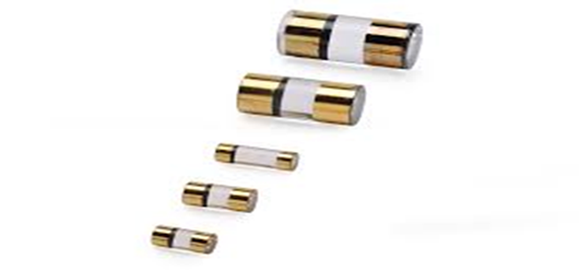
Fig.3. CRE KDDP crystals for Pockels cells with different apertures ( by INRAD Optics ).
The longitudinal electrooptic effect is a great advantage of KDDP crystal. Driving voltages U λ/2 are not dependent on the crystal dimensions and are the same for all Pockels cell apertures (Fig.3). This property can be very useful for various studies. This gives, for example, the possibility of constructing Pockels cells with large apertures at a very short crystal length.
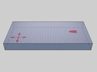
Since the driving voltages cannot be reduced by the choice of crystal geometry ( like in the case of transverse electrooptic effect), it can be realized by increasing the number of crystals in the cell. In practice, double-crystal designs of longitudinal KDDP Pockels cells are offered for some applications. In these designs, KDDP crystals are mounted in series and supplied with opposite directions of electric field (Fig.4 b).
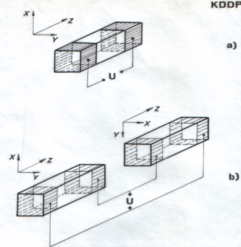
Fig.4. KDDP crystals of rectangular shape for Pockels cells with longitudinal electrooptic effect : a) for single crystal cell, b) for double-crystal cell.
KDDP (KD*P) crystals, that are grown from deuterated water solutions, are hygroscopic. Therefore, they require protection against atmospheric moisture. For this purpose, different technical solutions are used. KDDP crystals, generally are placed in appropriate hermetic housings.
In some technical solutions, crystals are mounted in housings closed by optical windows and filled with index-matching liquid to eliminate internal reflections. External surfaces of windows are antireflection (AR) coated. In other solutions KDDP crystals and optical windows are AR coated with reflectivity of < 0,25% per optical surface. KDDP crystals with high power Sol-Gel antireflection coatings are used.
All these solutions are widely used in flashlamp-pumped solid-state lasers as well as DPSS lasers.
Pockels cells using KDDP crystals can be also made in configuration with transverse electrooptic effect. This configuration is based on the r41 electrooptic coefficient and is realised as double-crystal design. Coefficient r41 is 3 times lower than r63, but the driving voltages can be reduced by selecting the crystal dimensions.
These constructions require using of both crystals with equal lengths of high accuracy. This is necessary to compensate for the natural birefringence. These configurations are also sensitive to temperature changes. Generally, transverse KDDP Pockels cells are mainly used as low-voltage modulators with small apertures.
Ryszard Wodnicki, PhD Eng.
References
[ 1 ] L.L. Steinmetz, T.W. Pouliot, B.C. Johnson, „Cylindrical, Ring-Electrode KD*P Electrooptic Modulator”, Applied Optics, Vol. 12, 7, pp. 1468-1471, (1973),
[ 2 ] Walter Koechner · Solid-State Laser Engineering, Springer Verlag .N.Y. , 1976.
[ 3 ] Z. Jankiewicz, E. Pelzner: „Modulator światła z wykorzystaniem wzdłużnego efektu elektrooptycznego Pockels’a” , Biuletyn WAT, vol. XXIX, Nr 1 (329), 1980, str. 21-32.
[ 4 ] R. S. Alnayli, Cs. Kuti, J.S. Bakos, I. Toth, „ Investigation of electric field distribution in Z-cut KDP Q-switch modulator crystals”. Quantum Electronics, 165(4), September 1989.
***

